From Guitar Case to Ceiling Rafters

I think in my last post I showed the construction of my Z scale guitar case layout.  I was going to add some scenery and a building or two, but I realized that having anything more than just the track and ballast would be damaged, loosened, or lost too easily.  That makes the guitar case layout officially DONE.

In recent weeks, I’ve begun formulating and constructing a new layout.  It is also in Z scale and uses foam, but it is almost all foam.  The entire base is the same blue 2″ insulation foam used in the guitar case layout.  The biggest difference and feature that makes it most unique is that is it to be a suspended layout that hangs from the ceiling of my basement via a pulley system.  It will have some pieces of plywood that connect the foam joints, and it will have to main bus wires running the interior length of the layout.  It wil also have sevearal stretches of grades that lead to a high grade loop.  It’s taken a lot of planning, mathematical calcuations, and messy foam and wood cutting, but I think it will look awesome!

Below are some photos of the layout’s early stages.img_6063

This is a sort of grid schematic.  I used basic notepad lines as units of measurements and basic mathematic X/Y axes to plan direction of travel.
img_6168

This project took most of the garage and a few hours to start, but it was worth the mess and effort.
img_6067

These are the products of my work.img_6069img_6086

I used a jig saw to cut everything so cleanly.  I would have thought my smaller and finer-toothed blade would be better for a clean cut, but it turns out that the big and jagged one worked far better.img_6065img_6108

Here is the basic shape.  it’s an oval with a side yard.img_6154

More to come!!!!!

Have Guitar, Will Play! …..Wait a Minute, That’s No Guitar!

It’s only been forever since I started this guitar case layout, but I’ve finally got one going in it.  This has been my first attempt at building a layout from scratch, and I have learned quite a bit.  Most importantly, the fine size of everything makes the biggest difference in operation because the tolerance of all the parts fitting together is key.

Firstly, cutting the piece of foam down to size (just under four feet by nearly one and a half feet) was mildly harder than I thought.  I measured the guitar case interior with some leeway.  The leather that encases the exterior of the wooden hand-made case bunches and bundles up inside, so I had to allow for that to snuggly and safely fit against the surface of the foam without tearing it up every time I pulled the foam out or placed it in.  I didn’t have my foam cutting wire on hand when I started, so I took a micro butane torch to a steak knife.  I heated the knife nearly to glowing hot and slowly sliced through the foam.  It took several tries because the metal cooled quickly in the coolness of my basement, and maintaining an even cut after starting and stopping several times was tougher than I expected.  I am definitely going to keep my foam cutting tool handier in the future.

This is the Marklín track pinned down for an initial test.  The locomotive is a Marklín Pennsylvania 4-6-2 Pacific.
img_5428

Forwardimg_5430img_5429Reverseimg_5431img_5433

I temporarily fastened the pieces of sectional track (which I would later regret) with tiny office supply pins so I could see and mark where to make holes for power leads.  The Marklïn track I used snapped together at the ends, and I thought that would work to my advantage.  However, I the track didn’t quite fit on the foam with enough clearance between the train and the frame of the case.  I had to lightly squeeze and flex the track into a tighter diameter, and the snaps didn’t want to hold very well.  I made it work and pinned everything down into the foam until I had the clearance and shape I wanted.  I connected my Rokuhan transformer to a single set of leads to test electrical continuity.  The locomotive ran decently, but there were so many inconsistencies in electrical flow and rail height that I decided to try soldering each piece of track together.  That helped, with the continuity, but the rail height was still a big problem.  I decided to pull it all out and start over with Micro Train Lines Flex track.

I cut some green and finely textured construction paper to glue onto the foam.  I chose to use the construction paper because this is layout is going to be mobile, and I don’t want to invest too much time and effort into something only to have it broken right away.  The paper looks nice enough for its intended purpose, and all I want is for this to be a fun layout.  After spreading Elmer’s glue down along the perimeter of the paper and foam base and letting it dry overnight, I soldered the flext track piece by piece as I pinned it down to the foam through the paper.  That worked much better all around, and I was happy with my track laying.

Ballasting was an exciting adventure.  I have a ballasting tool made specifically for Z scale.  It fits neatly around the rails and spreads ballast right up along them.  What I didn’t realize was how easily the fine ballast would be picked up by the open locomotive gears and stick in the gearbox.  I spend some extra time scraping ballast from between the rails with my solder scraper.  What a chore!  I’m going to modify that tool to not spread nearly so much between the rails.  LESSON LEARNED.

…to be continued!

“Big Things Have Small Beginnings”

As the line from Prometheus says, what started as a little plastic train set around a cake has become four sets occupying the better part of my apartment floor, and it keeps growing.

I believe I mentioned this in a previous post.  I am absolutely fascinated with Z scale.  It’s so much fun to look at all the detail that goes into this miniscule scale of such mammoth behemoths!  My modular layout is very nearly complete in its basic form.  All I really have left to do is adhere rare earth magnets around the edges of the foam boards.  The magnets will keep the boards from shifting when the layout is displayed, and it will keep everything together when it is folded up and in transit.

Pay no mind to my messy apartment.


I experimented with different ways of setting the ballast beneath the rails.  I tried spray-on adhesive, but the acid ate away at the foam.  I mixed ballast, Elmer’s glue, and vodka to make a sort of paste, and it sort of worked.  The traditional ballast spreading device was okay, but I think it would have worked better on uniformly level surfaces.  Oh, well.  One thing I did really like was using a dropper to soak the curing ballast with more alcohol to help the glue run more along the outline of the ties and trails.  I never intended this layout to be very detailed.  I can’t have too much to it, or it could make a mess if it were all knocked to the floor or broken.

It’s the Little Things. The VERY little things.

Of all the different sizes of model trains, I find the most fascinating to be Z scale.  It’s so small and minuscule, but it is also so mighty!  The little engines are so tiny, but they are deceptively fast and strong.  My first Z set was a Micro Trains Line Desktop Railroad Set with a New York Central F7 diesel.  I also bought a Western Pacific four-car wreck recovery pack.  I really enjoy my little train set.

I’ve noticed something about how the whole consist pulls.  It may be due to the angle of couplers, or merely the size of everything, but it seems that there needs to be enough weight to everything for the couplers to catch one another.  If they are not taught, they release and come undone.  The lack of weight is good for long loads and going in reverse with a lessened chance of derailment, but not so great for staying together.

From little to not so little, I am excited to get into two-rail O scale.  I have only one such item–my Rivarossi 0-8-0 Indiana Harbor Belt steamer.  I’ve heard from several that the two-rail O scale models look more like models than the those of the three-rail variety.  Based on the details I have observed in my engine, I am inclined to agree.  Even so, the track seems to be quite expensive.  It will take much saving to build my little railroad, but the time and money will be well worth the effort.


Let’s move on to bigger things.  A customer brought in two O scale locomotives.  He wanted one to get some regular maintenance as well as have a smoke unit installed.  I wasn’t quite sure if I could make one fit, but I did!  I just happened to already have two smoke units in my spare parts dish.  I was sure I would have to do a lot of form fitting, cutting, molding, possibly melting, and major rewiring to make it work.

As it turns out, all I needed to do was shim the whole frame of the engine.  The smoke unit just fit.  There is absolutely no room for any movement, jostling, spare wires–it could almost be air-tight.  But it fits.  It works.  And I didn’t have to do ANY drilling or filing.  The customer is sure to be happy.

Oh, and the engine, itself, works good as new, too.  Not that that was the whole point of bringing the thing in, or anything…………..


As for the other engine, it seemed to be much more of a challenge.  Fitting a new unit in the body was easy.  It even aligned with the smoke stack.  However, getting the mechanism to puff the smoke in equal and consistent puffs was more than adverse.  The new smoke unit fit, but it wasn’t shaped the same way.  The empty air reservoire that actually pushes the smoke up and out was offset in the old one and directly center in the new.  The lever that operates the reservoire column was too long and not correctly shaped to properly work with the new unit.  I tried flexing the lever and form filing the reservoire, but everything caught and stuck.

I was fidgeting with the old smoke unit, trying to figure it all out, when I dropped the thing to the floor, and the burner element fell out of the loose end cap.  Then, it hit me.  All I had to do was swap out the old wax melting element for the oil boiling one.  After much scraping and digging, the new element fit perfectly.  I soldered everything up, slapped the cap on, fit the rest of the engine back to the frame, and crossed my fingers.


’twas most awesome.

That same engine had a funky reversing unit.  I cracked it open, and everything was pretty dirty.  The funny thing about a reversing unit is the number of parts it takes to make an engine simply move.  The inner drum is lined with metal belts that are shaped to alternately contact metal flanges.  Each flange is soldered to a different wire that either provides electrical flow or redirects it somewhere else.  If a single one is bent out of shape or contacting the wrong belt, nothing works.  It all just sparks or sits dead.  The flanges took some flexing and sanding, but I got it all back into shape.  Pulling the drum out is easy.  Putting it back in is a pain.  The two walls that hold the drum in place have to be close enough to contact it, two flange boards have to fit into slots of the unit walls, the flanges have to be spaced wide enough to allow the drum to fit back into place, and the clip that rotates the drum has to be out of the way.  Much in the fashion of re-assembling steam engine drive rods, everything has to fit in just the right way at just the right time.


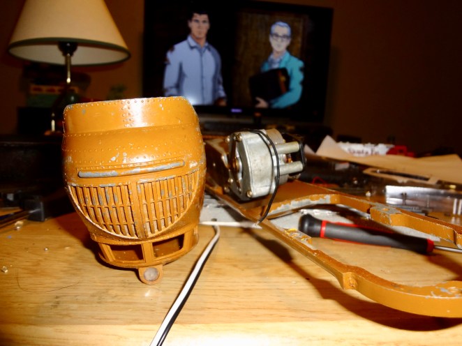
I really wish I had had the sense to take photos of the things I’ve been mentioning in this particular post.  Oh, well.  There will be plenty more photogenic opportunities.

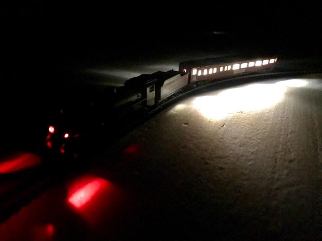
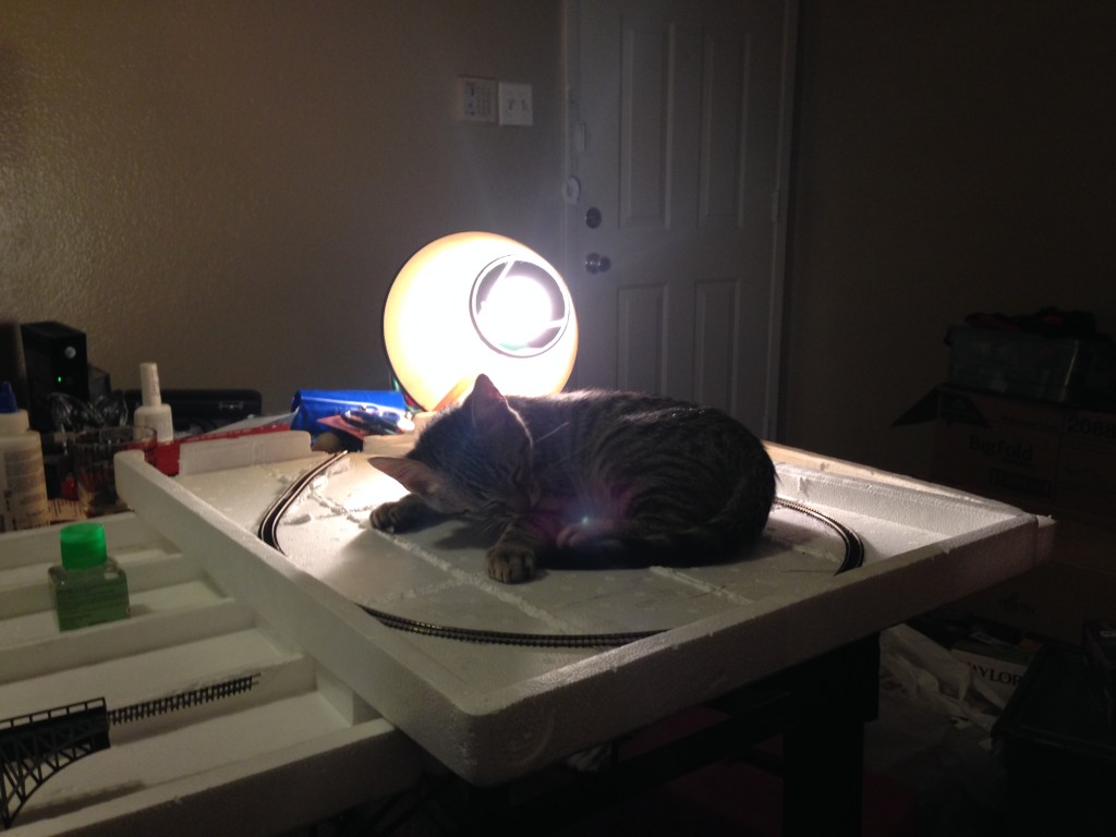
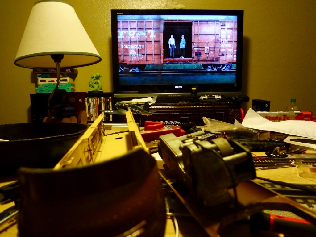
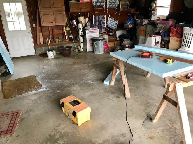
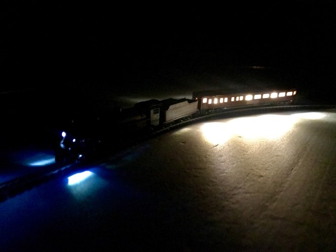
In the meantime, here are some photos of other things.
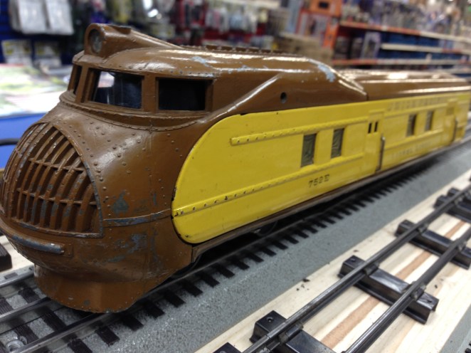
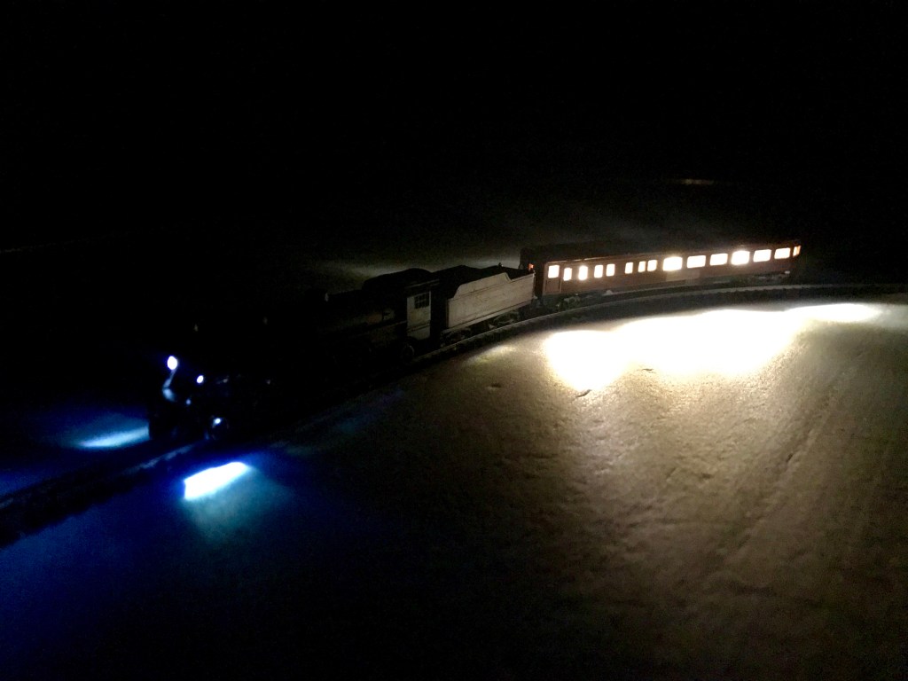
IMG_2453IMG_2434IMG_2433IMG_2430fullsizeoutput_2728fullsizeoutput_2729fullsizeoutput_272afullsizeoutput_272bIMG_2484fullsizeoutput_26c6